• Address

    C-188, Sector 31-D, P&T Society,

    Korangi Industrial Area,

    Karachi-74900,

    Pakistan


  • Call us on

     +92-21-35070751

     +92-300-5776703

  • Mail us @

    info@pakplc.com


Analog expansion board (A/D conversion, D/A conversion)

Model
(Number of channels)
Input specifications Applicable FX PLC
Item Input voltage Input current FX
3S
FX
3G
FX
3U
FX
3GC
FX
3UC
FX3G-2AD-BD
(Input 2 ch)
Input
range
0 to 10 V DC
(Input resistance 198.7 kΩ)
4 to 20 mA DC
(Input resistance 250 Ω)
*3

Max.
1 unit
*1*2

Max.
2 units
× × ×
Resolution 2.5 mV
(10 V/4000)
8 μA
{(20 - 4 mA)/2000}
FX3G-1DA-BD
(Output 1 ch)
Output
range
0 to 10 V DC
(External load resistance value
2 kΩ to 1 MΩ)
4 to 20 mA DC
(External load resistance value
500 Ω or less)
*3

Max.
1 unit
*1*2

Max.
2 units
× × ×
Resolution 2.5 mV
(10 V/4000)
8 μA
{(20 - 4 mA)/2000}

*1: Supported by FX3G ver. 1.10 and later.
*2: FX3G 14pt, 24pt models: 1 board. 40pt, 60pt models: 2 boards.
*3: Function expansion board and FX3S-CNV-ADP cannot be used together.


Mixed Analog Input/Output (A/D conversion, D/A conversion)

Model
(Number of channels)
Input/output specifications Applicable FX PLC
Item Input/output voltage Input/output current FX
3S
FX
3G
FX
3U
FX
3GC
FX
3UC
FX3U-3A-ADP
(Input 2 ch)
(Output 1ch)
Input
range
0 to 10 V DC
(Input resistance
198.7 kΩ)
4 to 20 mA DC
(Input resistance 250 Ω)
*7

Max.
1 unit
*1*6

Max.
2 units
*2

Max.
4 units

Max.
2 units
*3

Max.
4 units
Output
range
0 to 10 V DC
(External load resistance value
5 kΩ to 1 MΩ)
4 to 20 mA DC
(External load resistance value
500 Ω or less)
Resolution [Input voltage]
2.5 mV (10 V/4000)
[Output voltage]
2.5 mV (10 V/4000)
[Input current]
5 μA (16 mA/3200)
[Onput current]
4 μA (16 mA/4000)
FX2N-5A
(Input 4 ch)
(Output 1ch)
Input
range
-100 to 100 mV DC
-10 to 10 V DC
(Input resistance 200 kΩ)
-20 to 20 mA DC
4 to 20 mA DC
(Input resistance 250 Ω)
× ×
Max.
8 units
× *4*5

Max.
8 units
Output
range
-10 to 10 V DC
(External load resistance value
2 kΩ to 1 MΩ)
0 to 20 mA DC,
4 to 20 mA DC
(External load resistance value
500 Ω or less)
Resolution 50 μV
(at ±100 mV)
312.5 μV
(at ±10 V)
1.25 μA,10 μA
((depending on
mode used))


*1: Supported by FX3G ver.1.20 and later. For connection to FX3G, FX3G-CNV-ADP is required.
*2: Supported by FX3U ver.2.61 and later. For connection to FX3U, function expansion board is required.
*3: Supported by FX3UC ver.2.61 and later. When connecting to FX3UC- 32MT-LT(-2), function expansion board is required.
*4: When connecting to FX3UC, FX2NC-CNV-IF or FX3UC- 1PS-5V is required.
*5: FX3UC- 32MT-LT(-2): 7 units. FX3UC-**MT/D, FX3UC- **MT/DSS, FX3UC-16MR/D (S)-T: 8 units.
*6: FX3G 14 pt, 24 pt models: 1 board. 40 pt, 60 pt models: 2 boards.
*7: For connection to FX3S, FX3S-CNV-ADP is required.


Analog Input (A/D conversion)

Model
(Number of channels)
Input specifications Applicable FX PLC
Item Input voltage Input current FX
3S
FX
3G
FX
3U
FX
3GC
FX
3UC
FX3S-30MR/ES-2AD
FX3S-30MT/ES-2AD
FX3S-30MT/ESS-2AD
(Input 2ch)
Input
range
0 to 10 V DC
(Input resistance 115.7 kΩ)
- - - - - -
Resolution 10 mV
(10 V/1000)
-
FX2N-2AD
(Input 2 ch)
Input
range
0 to 10 V DC,
0 to 5 V DC
(Input resistance 200 kΩ)
The input characteristic is the same for each channel.
4 to 20 mA DC
(Input resistance 250 Ω)
The input characteristic is the same for each channel.
× ×
Max.
8 units
× *1*2

Max.
8 units
Resolution 2.5 mV
(10 V × 1/4000)
1.25 mV
(5 V × 1/4000)
4 μA
((20 - 4 mA) × 1/4000)
FX3U-4AD
(Input 4ch)
Input
range
-10 to 10 V DC
(Input resistance 200 kΩ)
-20 to 20 mA DC,
4 to 20 mA
(Input resistance 250 Ω)
× ×
Max.
8 units
× *1*2

Max.
8 units
Resolution 0.32 mV
(20 V × 1/64000)
1.25 μA
(40 mA × 1/32000)
FX3U-4AD-ADP
(Input 4ch)
Input
range
0 to 10 V DC
(Input resistance 194 kΩ)
4 to 20 mA DC
(Input resistance 250 Ω)
*8

Max.
1 unit
*4*3

Max.
2 units
*5

Max.
4 units

Max.
2 units
*5*6

Max.
4 units
Resolution 2.5 mV
(10 V/4000)
10 μA
(16 mA/1600)
FX3UC-4AD
(Input 4ch)
Input
range
-10 to 10 V DC
(Input resistance 200 kΩ)
4 to 20 mA DC,
-20 to 20 mA DC
(Input resistance 250 Ω)
× × × × *7*2

Max.
8 units
Resolution 0.32 mV
(20 V × 1/64000)
2.50 mV
(20 V × 1/8000)
1.25 μA
(40 mA × 1/32000)
5.0 μA
(40 mA × 1/8000)
FX2N-8AD
(Input 8 ch)
Input
range
-10 to 10 V DC
(Input resistance 200 kΩ)
4 to 20 mA DC
-20 to 20 mA DC
(Input resistance 250 Ω)
× ×
Max.
8 units
× *1*2

Max.
8 units
Resolution 0.63 mV
(20 V × 1/32000)
2.50 mV
(20 V × 1/8000)
2.5 μA
(40 mA × 1/16000)
2 μA
(16 mA × 1/8000)
5.0 μA
(40 mA × 1/8000)
4 μA
(16 mA × 1/4000)


*1: When connecting to FX3UC, FX2NC-CNV-IF or FX3UC- 1PS-5V is required.
*2: FX3UC- 32MT-LT(-2): 7 units. FX3UC-**MT/D, FX3UC- **MT/DSS, FX3UC-16MR/D (S)-T: 8 units.
*3: FX3G 14pt, 24pt models: 1 board. 40pt, 60pt models: 2 boards.
*4: When connecting to FX3G, FX3G-CNV-ADP is required.
*5: When connecting to FX3U, function expansion board is required.
*6: FX3UC- 32MT-LT supported from version 1.20 or later.
*7: FX3UC- 32MT-LT supported from version 1.30 or later.
*8: When connecting to FX3S, FX3S-CNV-ADP is required.


Analog Output (D/A conversion)

Model
(Number of channels)
Output specifications Applicable FX PLC
Item Output voltage Output current FX
3S
FX
3G
FX
3U
FX
3GC
FX
3UC
FX2N-2DA
(Output 2 ch)
Output
range
0 to 10 V DC,
0 to 5 V DC
(External load resistance value
2 kΩ to 1 MΩ)
4 to 20 mA DC
(External load resistance value
400 Ω or less)
× ×
Max.
8 units
× *1*2

Max.
8 units
Resolution 2.5 mV
(10 V × 1/4000)
1.25 mV
(5 V × 1/4000)
4 μA
((20 - 4) mA × 1/4000)
FX3U-4DA
(Output 4 ch)
Output
range
-10 to 10 V DC
(External load resistance value
1 kΩ to 1 MΩ)
0 to 20 mA DC
4 to 20 mA DC
(External load resistance value
500 Ωor less)
× ×
Max.
8 units
× *1*2

Max.
8 units
Resolution 0.32 mV
(20 V × 1/64000)
0.63 μA
(20 mA × 1/32000)
FX3U-4DA-ADP
(Output 4 ch)
Output
range
0 to 10 V DC
(External load resistance value
5 kΩ to 1 MΩ)
4 to 20 mA DC
(External load resistance value
500 Ω or less)
*7

Max.
1 unit
*3*4

Max.
2 units
*5

Max.
4 units

Max.
2 units
*5*6

Max.
4 units
Resolution 2.5 mV
(10 V/4000)
4 μA
(16 mA/4000)


*1: When connecting to FX3UC, FX2NC-CNV-IF or FX3UC- 1PS-5V is required.
*2: FX3UC- 32MT-LT(-2): 7 units. FX3UC-**MT/D, FX3UC- **MT/DSS, FX3UC-16MR/D (S)-T: 8 units.
*3: FX3G 14 pt, 24 pt models: 1 board. 40 pt, 60 pt models: 2 boards.
*4: When connecting to FX3G, FX3G-CNV-ADP is required.
*5: When connecting to FX3U, FX3UC-32MT-LT(-2), function expansion board is required.
*6: FX3UC- 32MT-LT supported from version 1.20 or later.
*7: When connecting to FX3S, FX3S-CNV-ADP is required.


Fx Communication

High-speed output special adapter

Model Number of
controlled axis
Maximum
frequency
Applicable FX PLC
FX
3S
FX
3G
FX
3U
FX
3GC
FX
3UC
FX3U-2HSY-ADP Independent two axes 200kHz × × *

Max.
2 units
× ×
 

*: When used together with analog or communication adapters, function expansion board is required


Pulse output block

Model Number of
controlled axis
Maximum
frequency
Applicable FX PLC
FX
3S
FX
3G
FX
3U
FX
3GC
FX
3UC
FX3U-1PG Independent one axis 200kHz × × *3

Max.
8 units
× *1*3

Max.
6 units
FX2N-10PG Independent one axis 1MHz(1 Hz to 1 MHz
differential line driver output)
× ×
Max.
8 units
× *1*2

Max.
8 units

*1: When connecting to FX3UC, FX2NC-CNV-IF or FX3UC-1PS-5V is required.
*2: FX3UC-32MT-LT(-2): 7 units. FX3UC-**MT/D,FX3UC-**MT/DSS,FX3UC-16MR/D(S)-T: 8 units.
*3: FX3U, FX3UC supported from version 2.20 or later.


SSCNET

Model Number of
controlled axis
Maximum
frequency
Applicable FX PLC
FX
3S
FX
3G
FX
3U
FX
3GC
FX
3UC
FX3U-20SSC-H Two axes
(Independent/Simultaneous)
- × ×
Max.
8 units
× *1*2

Max.
8 units

*1: When connecting to FX3UC, FX2NC-CNV-IF or FX3UC-1PS-5V is required.
*2: FX3UC-32MT-LT(-2): 7 units. FX3UC-**MT/D,FX3UC-**MT/DSS,FX3UC-16MR/D(S)-T: 8 units.


Positioning dedicated unit

Model Number of
controlled axis
Maximum
requency
Applicable FX PLC
FX
3S
FX
3G
FX
3U
FX
3GC
FX
3UC
FX2N-10GM Independent one axis 200kHz × ×
Max.
8 units
× *1*2

Max.
8 units
FX2N-20GM Two axes
(Independent/Simultaneous)
200kHz

*1: When connecting to FX3UC, FX2NC-CNV-IF or FX3UC-1PS-5V is required.
*2: FX3UC-32MT-LT(-2): 7 units. FX3UC-**MT/D,FX3UC-**MT/DSS,FX3UC-16MR/D(S)-T: 8 units


For FX2N-10GM/FX2N-20GM positioning teaching panel

Model Product
E-20TP-SET0
(with E-20TP-CAB0)
FX2N-10GM, FX2N-20GM
E-20TP-E-SET0
(with E-20TP-CAB0)

Angle control unit

Model Number of
controlled axis
Maximum
frequency
Applicable FX PLC
FX
3S
FX
3G
FX
3U
FX
3GC
FX
3UC
FX2N-1RM-SET*1 One axis 720 divisions/rotation (0.5 degree)
or 360 divisions/rotation (1 degree)
× ×
Max.
3 units
× *2*3

Max.
3 units
FX2N-1RM-E-SET*1

*1: FX2N-1RM-SET is a Japanese domestic only product. For use overseas, please select FX2N-1RM-E-SET, which supports overseas standards.
*2: Extension cable cannot be used.
*3: When connecting to FX3UC, FX2NC-CNV-IF or FX3UC-1PS-5V is required.
 

PLC built-in pulse output functions and positioning functions

Items FX3S FX3G,FX3GC FX3U,FX3UC
Number of axis Two axes [FX3G]
 Two axes (14/24 points)
 Three axes (40/60 points)
[FX3GC]
 Two axes
Three axes
Number of controlled axis Independent two axes [FX3G]
 Independent two axes (14/24 points)
 Independent three axes (40/60 points)
[FX3GC]
 Independent two axes
Independent three axes
Maximum frequency 100 kHz 100 kHz 100 kHz
Programming languages Sequence programs Sequence programs Sequence programs
Compatible main unit Transistor
output type
main unit
Transistor
output type
main unit
Transistor
output type
main unit
Pulse
output instruction
Pulse Y Output
(PLSY)
Acceleration/Deceleration Setup
Pulse Y Output
(PLSR)
Pulse output type Pulse train
(Direction is controlled
by PLC program)
Pulse train
(Direction is controlled
by PLC program)
Pulse train
(Direction is controlled
by PLC program)
Positioning
instruction
Absolute Current Value Read
([D]ABS)
Dog Search
Zero Return
(DSZR)
Zero Return
(ZRN)
*1 *1 *1
Variable Speed Pulse Output
(PLSV)
Drive to Increment
(DRVI)
Drive to Absolute
(DRVA)
Interrupt Positioning
(DVIT)
× ×
Batch Data Positioning Mode
([D]TBL)
× *2
Pulse output type Pulse train + direction Pulse train + direction Pulse train + direction
 

*1: No DOG search function Decelerate when near point DOG turns ON, and stop when near point DOG turns OFF (Different from zero return operation with zero signal count)
*2: FX3UC-32MT-LT supported from version 2.20 or later.

Optional parts and spare parts

Servo motor connection cable

Model Length Description
E-GMH-200CAB 2 m [MR-H series servo amplifer connection cable]
Can direcly connect FX2N-10GM/FX2N-20GM and servo amplifer.
I/O operation signal part has 20-pin connector for connection to Mtisubishi terminal block.
E-GMJ-200CAB 2 m [MR-J series servo amplifer connection cable]
Can direcly connect FX2N-10GM/FX2N-20GM and servo amplifer.
I/O operation signal part has 20-pin connector for connection to Mtisubishi terminal block.
E-GMJ2-200CAB1A 2 m [MR-J2, MR-J2-Super series servo amplifer connection cable]
Can direcly connect FX2N-10GM/FX2N-20GM and servo amplifer.
E-GMC-200CAB 2 m [MR-C series servo amplifer connection cable]
Can direcly connect FX2N-10GM/FX2N-20GM and servo amplifer.
I/O operation signal part has 20-pin connector for connection to Mtisubishi terminal block.
E-GM-200CAB 2 m [General purpose connection cable]
Has connector on both sides.
Can connect to general purpose drive unit via Mitsubishi terminal block.


Connector for self-manufactured I/O cable (an electric wire or a crimp tool is not enclosed.)

Model Description
FX2C-I/O-CON [Flat Cable Connector]
AWG28 (0.1 mm2): A set of 10 pcs

Crimp connector: FRC2-A020-3OS 1.27-pitch 20 cores

Crimp tool: Separately arrange the tool manufactured by DDK Ltd.
357J-4674D Main Unit
357J-4664N Attachment
FX2C-I/O-CON-S [Connector for bared wire]
AWG22 (0.3 mm2): 5 sets

Housing: HU-200S2-001
Crimp contact: HU-411S

Crimp tool: A product manufactured by DDK Ltd. is separately required.
357J-5538
FX2C-I/O-CON-SA [Connector for bared wire]
AWG20 (0.5mm2): 5 sets

Housing: HU-200S2-001
Crimp contact: HU-411SA
Crimp tool: A product manufactured by DDK Ltd. is separately required.
357J-13963

Extension connection cable

Model Length Description
FX2N-GM-65EC 65 cm [Connection extension cable between PLC and FX2N-10GM/FX2N-20GM]
One cable cable can be used in a system.
Standard connection cable (55mm) is included with FX2N-10GM/FX2N-20GM.
F2-RS-5CAB 5 m [Resolver extension cable for FX2N-1RM]
Resolver can be extended up to 100m extension by linking multiple cables.

Connection cable for peripheral devices

Model Length Description
(1) E-20TP-CAB0 3 m [E-20TP connection cable]
FX2N-10GM/FX2N-20GM (MINI DIN 8-pin) ⇔ E-20TP (MINI DIN 8-pin)
Cable length is different between (1) and (2).
(1) E-20TP-CAB0 (3 m) is included with E-20TP-SET0.
(2) FX-20P-CAB0 1.5 m

Spare parts

Model Length Description
FX2N-GM-5EC 55 mm [Connection cable between PLC and FX2N-10GM/20GM]
One cable is included with FX2N-10GM/20GM.


Universal Model QCPU

Lineup

Model Program capacity Device capacity
(Standard device
+Standard RAM)
Standard ROM capacity No. of I/O points Basic operation processing speed (LD instruction) Peripheral connection ports*1 Memory card I/F
Q26UDVCPU 260K
steps
700K words
(60K+640K)
4102K
bytes
4096 points 1.9ns USB Ethernet SD memory card
(SD memory card,
SDHC memory card)
*2
Q13UDVCPU 130K
steps
572K words
(60K+512K)
2051K
bytes
USB Ethernet
Q06UDVCPU 60K
steps
424K words
(40K+384K)
1025.5K
bytes
USB Ethernet
Q04UDVCPU 40K
steps
168K words
(40K+128K)
USB Ethernet
Q03UDVCPU 30K
steps
126K words
(30K+96K)
USB Ethernet
Q100UDEHCPU 1000K
steps
925K words
(29K+896K)
16384K
bytes
9.5ns USB Ethernet feature icon memory (SRAM card,
FLASH card,
ATA card)
Q50UDEHCPU 500K
steps
797K words
(29K+768K)
8092K
bytes
USB Ethernet
Q26UDEHCPU 260K
steps
669K words
(29K+640K)
4096K
bytes
USB Ethernet
Q26UDHCPU USB RS-232
Q20UDEHCPU 200K
steps
USB Ethernet
Q20UDHCPU USB RS-232
Q13UDEHCPU 130K
steps
541K words
(29K+512K)
2048K
bytes
USB Ethernet
Q13UDHCPU USB RS-232
Q10UDEHCPU 100K
steps
USB Ethernet
Q10UDHCPU USB RS-232
Q06UDEHCPU 60K
steps
413K words
(29K+384K)
1024K
bytes
USB Ethernet
Q06UDHCPU USB RS-232
Q04UDEHCPU 40K
steps
157K words
(29K+128K)
USB Ethernet
Q04UDHCPU USB RS-232
Q03UDECPU 30K
steps
125K words
(29K+96K)
20ns USB Ethernet
Q03UDCPU USB RS-232
Q02UCPU 20K
steps
93K words
(29K+64K)
512K
bytes
2048 points 40ns USB RS-232
Q01UCPU 15K
steps
1024 points 60ns USB RS-232
Q00UCPU 10K
steps
80ns USB RS-232
Q00UJCPU 29K words 256K
bytes
256 points 120ns USB RS-232

*1: The USB port terminal is mini-B.
*2: The operation of devices that are not manufactured or recommended as compatible products by Mitsubishi Electric cannot be guaranteed.


Input modules, Interrupt module

Point DC input DC/AC input AC input
5 V DC 5/12 V DC 24 V DC 48 V DC/AC 100...120 V AC 100...120 V AC
Positive Negative Positive/
Negative
Positive Negative Positive/
Negative
8 points QX48Y57*1 QX28
16 points QX70H QX90H QX70 QX40
QX40-TS
QX40-S1
QX40H
QI60
QX80
QX80H
QX80-TS
QX50 QX10
QX10-TS
32 points QX71 QX41
QX41-S1
QX41-S2
QH42P*1
QX41Y41P*1
QX81
QX81-S2
64 points QX72 QX42
QX42-S1
QX82
QX82-S1

*1: Input specifications for I/O combined modules


Output modules

Point Contact output TRIAC output Transistor output
24 V DC, 240 V AC 100...240 V AC 5...12 V DC 5...24 V DC 12...24 V DC
Sink type Sink type Sink/Source type Sink type Source type
7 points QX48Y57*2
8 points QY18A QY68A
16 points QY10
QY10-TS
QY22 QY70 QY40P
QY40P-TS
QY50
QY80
QY80-TS
32 points QY71 QY41H QY41P
QH42P*2
QX41Y41P*2
QY81P
64 points QY42P QY82P

*2: Output specifications for I/O combined modules

●High speed DC input module (positive common type) QX40H QX70H

●High speed DC input module (negative common type) QX80H QX90H

Speed up control by catching the input signal variation at 0 ms*3.
Two devices with differing power systems can be connected to the same module using different 8 point common terminals.

*3: The actual response time is 5 µs delay when turning ON, 10 µs delay when turning OFF, because the hardware response time is added.

Common type Input voltage
24 V DC 5 V DC
Positive QX40H QX70H
Negative QX80H QX90H
 

●Spring clamp terminal block type input module QX10-TS QX40-TS QX80-TS

●Spring clamp terminal block type output module QY10-TS QY40P-TS QY80-TS

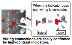
Spring clamp terminal blocks visually indicate the connection status. Also, by eliminating screws, wiring and maintenance work is made easier.

Advantages of spring clamp terminal blocks

Advantages of spring clamp terminal blocks

  • Impervious to vibration, secured wiring connections.
  • Eliminating screws greatly simplifies conventional maintenance.


  • Siemens
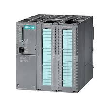
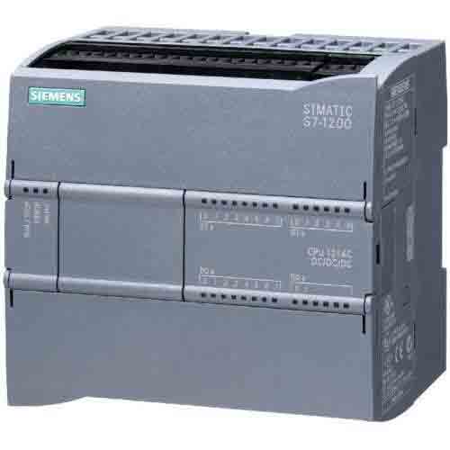
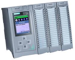
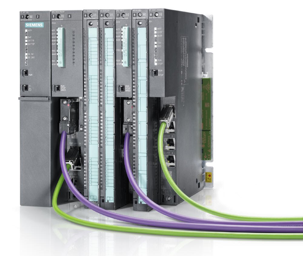
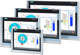
Siemens offers a wide range of Programmable Logic Controllers (PLC). S7-1200 PLC is suitable for small individual machine applications, whereas S7-300 PLC was previously targeted towards medium to high demand applications. However since it is nearing its end-of-lifecycle, S7-300/400 PLC series have been supplemented with the innovative S7-1500 PLC series. A new range of HMI panels are also available in all sizes for suitable operator control/monitoring. S7-1200 and S7-1500 are both part of Totally Integrated Automation (TIA) platform and programmable via Siemens TIA Portal software.
Simatic 300

          SIMATIC S7-300

 
Simatic 1200

         SIMATIC S7-1200

 
Simatic 1500

         SIMATIC S7-1500


s7 400

          SIMATIC S7-400

 
Simatic HMI

          SIMATIC HMI